Radiation, Light and Illumination Visual Map
Visual Map
Section titled “Visual Map”Review layer: candidate figure references are OCR/PDF-text leads. Promoted crops are documentary scan crops that still need second-pass bibliographic and crop-coordinate review. Modern guide diagrams are explanatory reconstructions, not historical figure evidence.
Promoted original crops.
Candidate figure references.
Modern guide diagrams keyed here.
Formula candidates in the same source.
Promoted Original Crops
Section titled “Promoted Original Crops”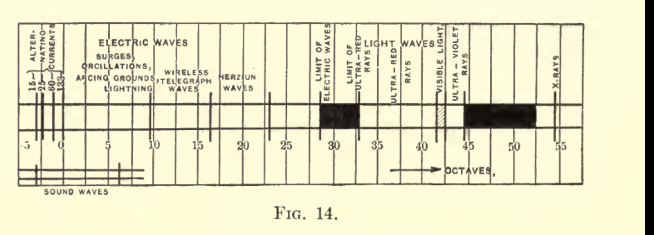
Radiation, Light and Illumination, printed page 18, Fig. 14
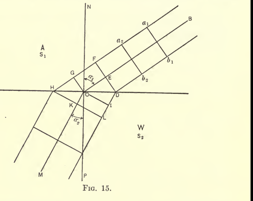
Radiation, Light and Illumination, printed page 22, PDF page 42; Fig. 15
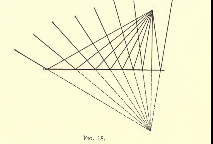
Radiation, Light and Illumination, printed page 28, PDF page 48; Fig. 18
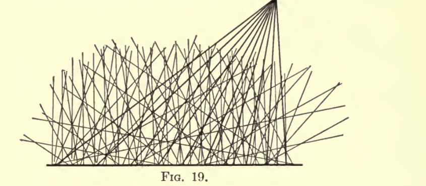
Radiation, Light and Illumination, printed page 29, PDF page 49; Fig. 19
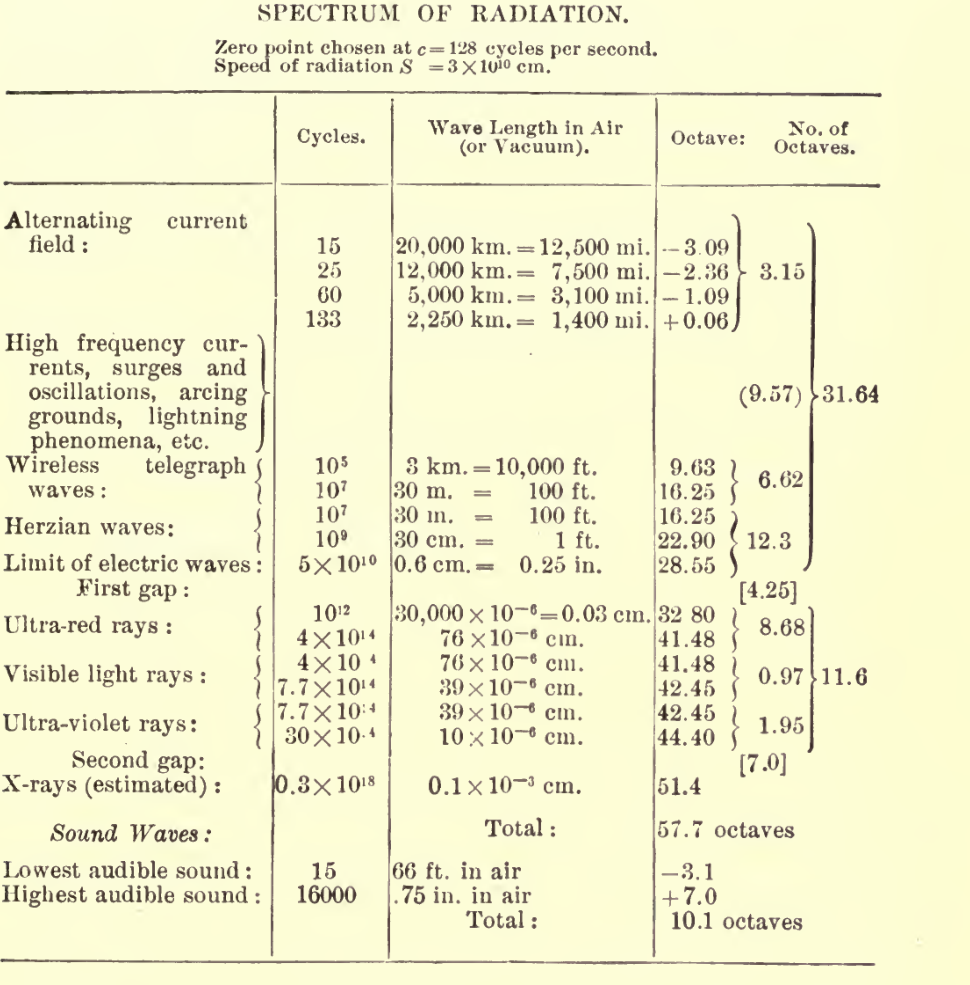
Radiation, Light and Illumination, printed page 17, PDF page 37; Spectrum of Radiation table preceding Fig. 14
Modern Guide Diagrams Keyed To This Source
Section titled “Modern Guide Diagrams Keyed To This Source”
Modern navigation guide for Steinmetz’s electric-wave, visible-light, ultraviolet, and X-ray spectrum bridge.
radiation, electric-waves, frequency, spectrum, ether

Modern guide for the practical bridge from radiation to visual illumination and light distribution.
illumination, radiation, light-flux, inverse-square
Candidate Figure References
Section titled “Candidate Figure References”| Candidate | Caption lead | Section | Routes |
|---|---|---|---|
radiation-light-and-illumination-fig-001Fig. 1 | tion, the time at which the moon M should disappear from sight, FIG. 1. when seen from the earth E, by passing behind Jupiter, 7 (Fig. 1), could be exactly calculated. It was found, however, that some- | Lecture 1: Nature And Different Forms Of Radiation | source workbench |
radiation-light-and-illumination-fig-002Fig. 2 | 5_MOE_S FIG. 2. direction the light reappears. If the disk is slowly revolved, alter- nate light and darkness will be observed, but when the speed in- | Lecture 1: Nature And Different Forms Of Radiation | source workbench |
radiation-light-and-illumination-fig-003Fig. 3 | from the upper surface of the plain glass plate A. A beam of FIG. 3. reflected light a, thus is a combination of a beam b and a beam c. | Lecture 1: Nature And Different Forms Of Radiation | source workbench |
radiation-light-and-illumination-fig-004Fig. 4 | glass plates. At those points dv dv etc. at which the distance FIG. 4. between the two glass plates is J wave length, or j, J, etc., the | Lecture 1: Nature And Different Forms Of Radiation | source workbench |
radiation-light-and-illumination-fig-005Fig. 5 | etc. in the plane of the paper, and thus perpendicular to the ray FIG. 5. of light. In the former case (a longitudinal vibration, as sound) there obviously can be no difference between the directions at | Lecture 1: Nature And Different Forms Of Radiation | source workbench |
radiation-light-and-illumination-fig-009Fig. 9 | it to you, by bringing the rods near to this Crookes’ radiometer, FIG. 9. which is an instrument showing the energy of radiation. It con- sists (Fig. 10) of four aluminum vanes, mounted in a moderately | Lecture 1: Nature And Different Forms Of Radiation | source workbench |
radiation-light-and-illumination-fig-010Fig. 10 | (red, orange and yellow) with increase in temperature, the light FIG. 10. 12 | Lecture 1: Nature And Different Forms Of Radiation | source workbench |
radiation-light-and-illumination-fig-011Fig. 11 | of the lower frequencies of visible radiation, red or orange. FIG. 11. In the tungsten lamp at high brilliancy and more still in the | Lecture 1: Nature And Different Forms Of Radiation | source workbench |
radiation-light-and-illumination-fig-012Fig. 12 | They are used in wireless telegraphy, etc. I here connect (Fig. 12) FIG. 12. the condenser C of the apparatus which I used for operating the ultra-violet arc, to a spark gap Gv of which the one side is con- | Lecture 1: Nature And Different Forms Of Radiation | source workbench |
radiation-light-and-illumination-fig-013Fig. 13 | o — ^^ — o FIG. 13. has been measured by Herz by producing standing waves by combination of main wave and reflected wave. | Lecture 1: Nature And Different Forms Of Radiation | source workbench |
radiation-light-and-illumination-fig-014Fig. 14 | as far as possible when producing light, as they consume power FIG. 14. and so lower the efficiency; the ultra-violet rays are of importance in medicine as germ killers. They are more or less destructive | Lecture 1: Nature And Different Forms Of Radiation | source workbench |
radiation-light-and-illumination-fig-015Fig. 15 | edge of the beam reaches the boundary at D its speed changes FIG. 15. by entering the medium W — decreases in the present instance. Let then Sl = speed of propagation in medium A, S2 = speed of | Lecture 2: Relation Of Bodies To Radiation | source workbench |
radiation-light-and-illumination-fig-016Fig. 16 | medium into another, and the higher frequencies are deflected FIG. 16. more than the lower frequencies, thus showing that the velocity of propagation decreases with an increase of frequency, that is, | Lecture 2: Relation Of Bodies To Radiation | source workbench |
radiation-light-and-illumination-fig-017Fig. 17 | VIOLET FIG. 17. a number of very faint red and orange lines, of which three are indicated dotted in Fig. 17. | Lecture 2: Relation Of Bodies To Radiation | source workbench |
radiation-light-and-illumination-fig-018Fig. 18 | perature rise, their brilliancy is greatly increased. FIG. 18. Combinations of the different types of spectra: continuous spectrum, line spectrum, band spectrum, reversed spectrum, | Lecture 2: Relation Of Bodies To Radiation | source workbench |
radiation-light-and-illumination-fig-019Fig. 19 | and the body thus acts as a mirror, that is, gives a virtual image FIG. 19. back of it as shown in dotted line in Fig. 18. In the latter case (Fig. 19) the light is reflected irregularly in all directions. | Lecture 2: Relation Of Bodies To Radiation | source workbench |
radiation-light-and-illumination-fig-021Fig. 21 | VIOLET FIG. 21. in the ultra-red and ultra-violet, where no power of radiation can produce visibility. It thus varies about as indicated in Fig. 22. | Lecture 3: Physiological Effects Of Radiation | source workbench |
radiation-light-and-illumination-fig-022Fig. 22 | the basis of equal ease in distinguishing objects. As the pur- FIG. 22. pose for which light is used is to distinguish objects, the correct comparison of lights obviously is on the basis of equal distinctness | Lecture 3: Physiological Effects Of Radiation | source workbench |
radiation-light-and-illumination-fig-023Fig. 23 | v FIG. 23. meter candles (or rather log i) as abscissas, for red light, wave length 65.0; orange yellow light, wave length 59; bluish green | Lecture 3: Physiological Effects Of Radiation | source workbench |
radiation-light-and-illumination-fig-024Fig. 24 | \ FIG. 24. (1 meter-candle is the illumination produced by 1 candle power | Lecture 3: Physiological Effects Of Radiation | source workbench |
radiation-light-and-illumination-fig-025Fig. 25 | S FIG. 25. 62 for high intensities and changes in approximately the same range of intensities in which lwo changes; ks is also plotted in | Lecture 3: Physiological Effects Of Radiation | source workbench |
radiation-light-and-illumination-fig-026Fig. 26 | YELLOW GREEN FIG. 26. carbon filament would be somewhat like C. That is, the physio- | Lecture 3: Physiological Effects Of Radiation | source workbench |
radiation-light-and-illumination-fig-027Fig. 27 | fore, increase enormously with the increase of temperature. FIG. 27. With bodies in a vacuum, the radiation power is the power input and this above law can be used to calculate the tempera- | Lecture 5: Temperature Radiation | source workbench |
radiation-light-and-illumination-fig-028Fig. 28 | weight, exhibit a periodicity in their properties which permits FIG. 28. a systematic study of their properties. In diagram Fig. 28 the | Lecture 5: Temperature Radiation | source workbench |
radiation-light-and-illumination-fig-029Fig. 29 | \\ FIG. 29. power required to maintain the temperature is correspondingly less, hence the efficiency is the same and merely a larger radiator | Lecture 5: Temperature Radiation | source workbench |
radiation-light-and-illumination-fig-030Fig. 30 | where colored radiation or luminescence is present. Thus the FIG. 30. radiation given by the interior of a closed body of uniform tem- perature ceases to be black body radiation if the interior is filled | Lecture 5: Temperature Radiation | source workbench |
radiation-light-and-illumination-fig-031Fig. 31 | one, the other from the other terminal. They are stationary FIG. 31. only if the gas pressure is perfectly constant, but separate and contract with the slightest change of pressure, hence are almost | Lecture 6: Luminescence | source workbench |
radiation-light-and-illumination-fig-032Fig. 32 | II II FIG. 32. decreasing gas pressure the voltage consumed in the space be- | Lecture 6: Luminescence | source workbench |
radiation-light-and-illumination-fig-033Fig. 33 | and you see the striated Geissler discharge through mercury FIG. 33. vapor appear between terminals 2 and 3, giving the green light> of the mercury spectrum. The terminals are quiet, as they do | Lecture 6: Luminescence | source workbench |
radiation-light-and-illumination-fig-034Fig. 34 | 3J=10 OHMS FIG. 34. and the spectrum of the arc is the spectrum of the negative ter- minal. An exception herefrom, occurs only in those cases in | Lecture 6: Luminescence | source workbench |
radiation-light-and-illumination-fig-035Fig. 35 | tendency exists of shifting the starting point, and the arc becomes FIG. 35. LUMINESCENCE. | Lecture 6: Luminescence | source workbench |
radiation-light-and-illumination-fig-036Fig. 36 | lished by the vapor stream coming from the negative. Thus the FIG. 36. arc can be started by merely starting a conducting vapor stream from the negative, as by an auxiliary arc. As soon as this con- | Lecture 6: Luminescence | source workbench |
radiation-light-and-illumination-fig-037Fig. 37 | draw it out until the arc flame wraps itself all around terminal FIG. 37. B} but the arc does not transfer. I even insert 10 ohms resist- ance rl in series with C (Fig. 37), so that the voltage AB is about | Lecture 6: Luminescence | source workbench |
radiation-light-and-illumination-fig-038Fig. 38 | ws FIG. 38. negative, that is, at a higher potential difference and a shorter distance against A than B is. I even hold C for some time in | Lecture 6: Luminescence | source workbench |
radiation-light-and-illumination-fig-039Fig. 39 | MAA FIG. 39. current during one half-wave only, but no current at all dur- ing .the other. I show you this experimentally, using 50 volts | Lecture 6: Luminescence | source workbench |
radiation-light-and-illumination-fig-040Fig. 40 | 60 CYCLES FIG. 40. terminals. The cause is obvious: to maintain an arc between | Lecture 6: Luminescence | source workbench |
radiation-light-and-illumination-fig-041Fig. 41 | and thereby increasing radiation, etc. For a 13-mm. (0.5-in.) FIG. 41. arc it is approximately shown as Curve II in Fig. 41 : 20 volts | Lecture 6: Luminescence | source workbench |
radiation-light-and-illumination-fig-043Fig. 43 | cannot freely condense, the mercury vapor pressure rises and FIG. 43. presses the mercury level down in the center tubes, up in the outside tubes, as indicated at b in Fig. 43, and thereby | Lecture 6: Luminescence | source workbench |
radiation-light-and-illumination-fig-044Fig. 44 | *m FIG. 44. to a bright pinkish-red arc, and the spectroscope shows that the spectrum lines in the red and orange have greatly increased in | Lecture 6: Luminescence | source workbench |
radiation-light-and-illumination-fig-045Fig. 45 | 1 0 FIG. 45. arc length, I, we get tor every value of current, i, a practically straight line, as shown for the magnetite arc in Fig. 45, for values | Lecture 8: Arc Lamps And Arc Lighting | source workbench |
radiation-light-and-illumination-fig-047Fig. 47 | 1J5 IN. FIG. 47. lengths, however, the observed values of voltage drop below the straight line, as shown in Fig. 47, and converge towards a | Lecture 8: Arc Lamps And Arc Lighting | source workbench |
radiation-light-and-illumination-fig-049Fig. 49 | arc. Thus comparing in Fig. 49 a 1-in. carbon arc A with a FIG. 49. 0.5-in. carbon arc B, the former requires, at 5 amperes, 112 volts and 560 watts, the latter only 84 volts and 420 watts, | Lecture 8: Arc Lamps And Arc Lighting | source workbench |
radiation-light-and-illumination-fig-050Fig. 50 | 154 RADIATION, LIGHT, AND ILLUMINATION. FIG. 50. FIG. 51a. | Lecture 8: Arc Lamps And Arc Lighting | source workbench |
radiation-light-and-illumination-fig-052Fig. 52 | 70. With the luminous arc, in which the light is proportional FIG. 52. 158 | Lecture 8: Arc Lamps And Arc Lighting | source workbench |
radiation-light-and-illumination-fig-054Fig. 54 | \r FIG. 54. ous height follow each other. Thus with an average arc volt- age of 75, momentary peaks of 85 volts will probably be reached | Lecture 8: Arc Lamps And Arc Lighting | source workbench |
radiation-light-and-illumination-fig-055Fig. 55 | as shown diagrammatically in its simplest form in Fig. 55, the FIG. 55. two white screens A and B are illuminated, the one, A, by the light, L, which is to be tested, the other, B, by the standard S, | Lecture 9: Measurement Of Light And Radiation | source workbench |
radiation-light-and-illumination-fig-057Fig. 57 | accuracy. FIG. 57. 78. When comparing lamps giving light of the same color, as incandescent lamps of the same filament temperature, that is, | Lecture 9: Measurement Of Light And Radiation | source workbench |
radiation-light-and-illumination-fig-058Fig. 58 | MEASUREMENT OF LIGHT AND RADIATION. 175 FIG. 58. the photometer may be used as far as it agrees with the lumi- | Lecture 9: Measurement Of Light And Radiation | source workbench |
radiation-light-and-illumination-fig-059Fig. 59 | Fig. 59, is the distribution curve in one meridian, it is the same FIG. 59. in every other meridian, and for photometric test of the illumi- nant it is sufficient to measure the light intensities in one merid- | Lecture 9: Measurement Of Light And Radiation | source workbench |
radiation-light-and-illumination-fig-060Fig. 60 | the former, giving a horizontal or equatorial distribution of FIG. 60. light intensity about as shown in Fig. 60. In this case the horizontal distribution curve may also be determined photo- | Lecture 9: Measurement Of Light And Radiation | source workbench |
radiation-light-and-illumination-fig-061Fig. 61 | side — minimum — intensity. Such curves are shown in Fig. 61. FIG. 61. This, however, carried out for every angle in the meridian, makes arc-light photometry rather laborious, especially as | Lecture 9: Measurement Of Light And Radiation | source workbench |
radiation-light-and-illumination-fig-062Fig. 62 | is: FIG. 62. = 27r/sin<M^ | Lecture 10: Light Flux And Distribution | source workbench |
radiation-light-and-illumination-fig-064Fig. 64 | 192 RADIATION, LIGHT, AND ILLUMINATION. FIG. 64. FIG. 65. | Lecture 10: Light Flux And Distribution | source workbench |
radiation-light-and-illumination-fig-065Fig. 65 | FIG. 64. FIG. 65. FIG. 66. | Lecture 10: Light Flux And Distribution | source workbench |
radiation-light-and-illumination-fig-066Fig. 66 | FIG. 65. FIG. 66. LIGHT FLUX AND DISTRIBUTION. 193 | Lecture 10: Light Flux And Distribution | source workbench |
radiation-light-and-illumination-fig-067Fig. 67 | direction. FIG. 67. Straight Line or Cylindrical Radiator. | Lecture 10: Light Flux And Distribution | source workbench |
radiation-light-and-illumination-fig-068Fig. 68 | 24 deg. above the horizontal, or in the space between a and a’ in Fig. 68. It is interesting to compare the three radiators, (1), (2), and (5), on the basis of equal maximum intensity, and on the basis of | Lecture 10: Light Flux And Distribution | source workbench |
radiation-light-and-illumination-fig-070Fig. 70 | > FIG. 70. FIG. 71. | Lecture 10: Light Flux And Distribution | source workbench |
radiation-light-and-illumination-fig-071Fig. 71 | FIG. 70. FIG. 71. In Fig. 72 is plotted the intensity distribution in the meridian | Lecture 10: Light Flux And Distribution | source workbench |
radiation-light-and-illumination-fig-072Fig. 72 | (7) Single-Loop Filament. FIG. 72. 200 | Lecture 10: Light Flux And Distribution | source workbench |